 English
 中文
中文







Precision Engineered Ceramics: From Drawing to Repeatable Production

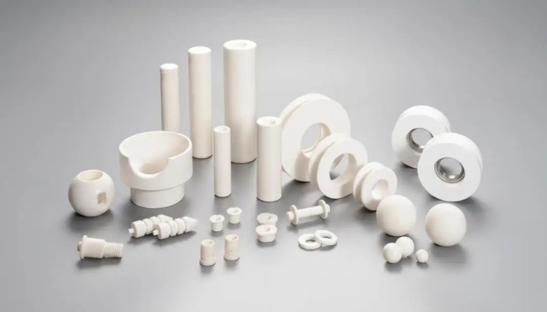
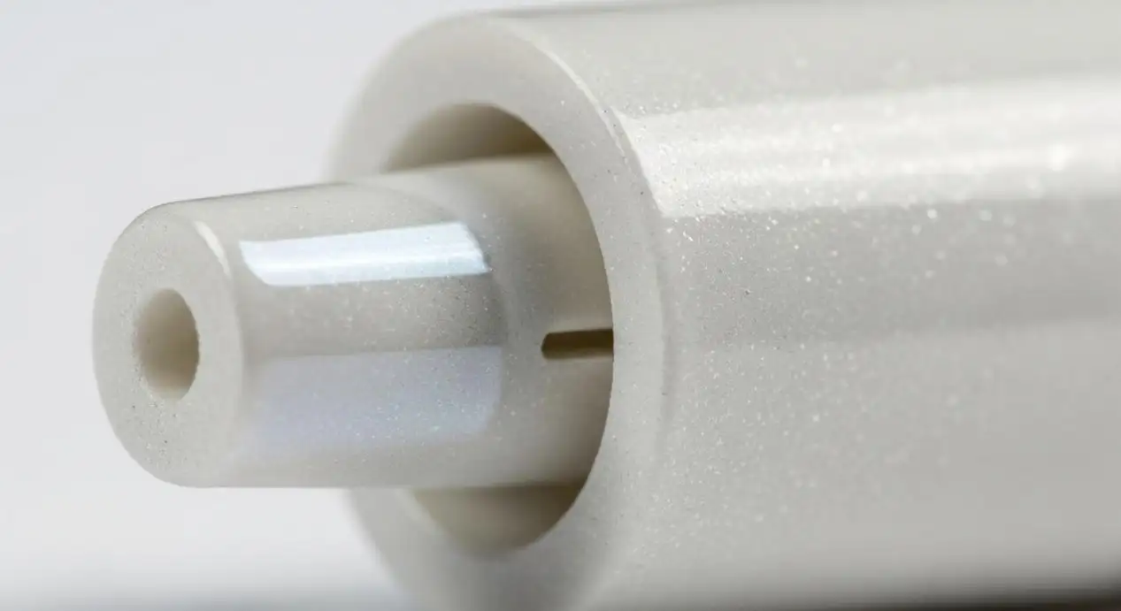
Precision engineered ceramics are used when components require controlled dimensional, geometric, surface, and functional performance in addition to basic material properties such as hardness, heat resistance, or electrical insulation.The component should be capable of predictable accuracy in locating, guiding, sealing, isolating or aligning other components.
It’s also harder to get that result than it is to machine a metal object. The ceramic powder is molded and sintered prior to obtaining the final size. The final part can be influenced by the type of shrinkage, part distortion, grinding strategy and measurement method. Precision starts not only during the machining process, but also during the final inspection and when the product is in volume production.
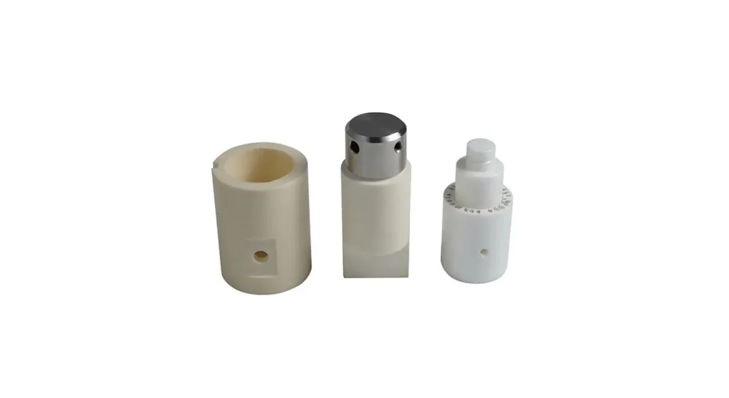
There must be a clear definition of precision, depending on what its function is.
A drawing can have lots of dimensions, but not every dimension has the same impact on component performance.These can be used to set up optical alignment, bearings fit, sealing pressure, electrical clearance and positioning requirements in semiconductor-related equipment.
Prior to production, the engineering team needs to determine:
- Assembly datums
- Critical mating diameters
- Features of alignment and positioning.
- Surfaces that control friction and wear
- Required electrical clearances
- Zones of concern for contamination
This rational organization allows unnecessary grinding to be avoided. This also provides a clear foundation for the supplier to choose the forming, machining and inspection process.
UPCERA’s custom ceramic parts showcase the various holes, steps, surfaces and special geometries it can create based on an application-specific drawing.
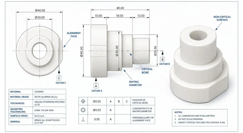
Set up a Clear Datum System
It is not possible to consistently verify precision without reference features agreed upon. When the manufacturer and the customer measure from different surfaces on a part, then they can get valid but conflicting results.
Primary, Secondary and Tertiary datums on a drawing should represent the location of the ceramic component in final assembly. All dimensions that represent the same function need to be referenced off of the same datum structure.
In some instances (e.g., a ceramic sleeve may need the bore and outer diameter to be concentric, a stepped locating component may need to have multiple diameters controlled along one centerline), it is necessary to control multiple diameters from a single centerline. The datum strategy should be representative of the manner in which the part is supported and loaded during use.
Account for Sintering Shrinkage Before Final Machining
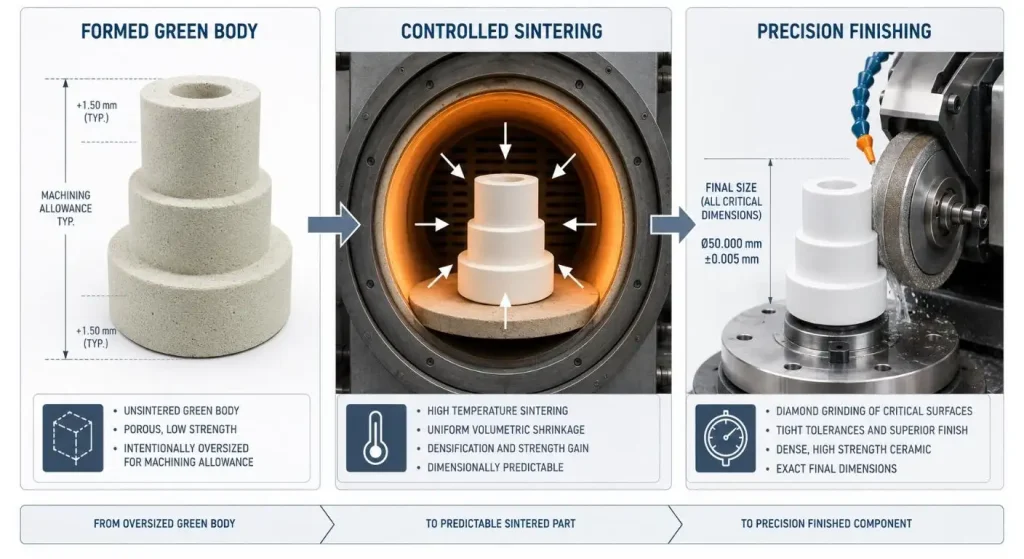
Sintering shrinkage results from densification of the ceramic body during firing.
This is a natural shrinkage and needs to be forecasted and managed. Dimensional variation or distortion can occur due to uneven green density, wall-thickness variations and firing position.
Shrinkage compensation is built into forming dimensions, tooling, and controlled sintering profiles.Some features that do not need a high degree of accuracy can be done during forming or green machining. Typically, critical features are completed following the sintering process.
The combination will not cause grinding of all the surfaces, while maintaining accuracy in the areas that matter. The advanced ceramic machining overview article from UPCERA provides an understanding of the relationship between the powder preparation, forming, sintering and precision finishing.
Use Geometric Tolerances, Not Dimensions Alone
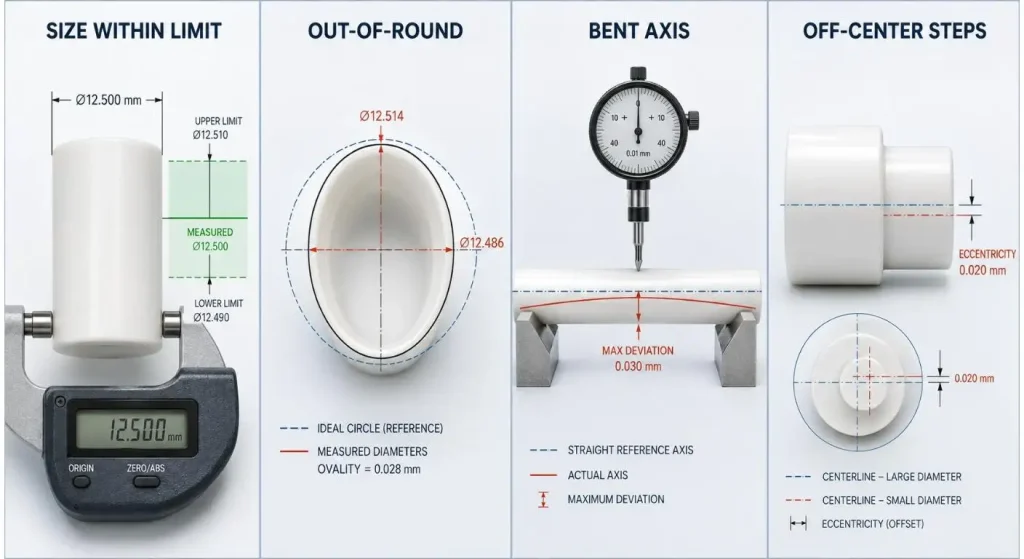
A component may still be unsuitable for assembly even when its size dimensions are within tolerance.Surface can be oval, tapered, curved or off axis.
These functional relationships are more effectively conveyed by geometric controls:
- Roundness controls the form of rotating or sealing surfaces.
- Long rods and guide components are controlled by straightness.
- Flatness helps ensure stable contact and sealing.
- In the case of plates and spacing components, parallelism plays a crucial role.
- Concentricity or runout- is to ensure that more than one diameter is aligned.
- Perpendicularity is used for controlling shoulders and mounting faces
Tight geometric tolerances should be applied only to functionally critical features.Implementing micron level geometry across the drawing actually raises machining, fixturing and inspection costs, but doesn’t necessarily lead to better products.
Match Surface Finish with Its Job
Surface roughness has an effect on friction, sealing, optical properties, cleanliness and bonding. But, a very low roughness value is not necessarily to the advantage.
To minimize wear, a sliding surface may be polished. There is a need for both low roughness and controlled flatness for a sealing face. The bonding surface can work more effectively with a certain texture as opposed to mirror finish.
The manufacturing process also needs to maintain the surface integrity. Chips, scratches or subsurface damage can occur from aggressive grinding and reduce a dimensionally correct component’s strength. Therefore, the selection of diamond tools, the control of coolant and finishing sequence should also be included in the engineering specification.
Choose Materials that are Manufacturable.
The precision and cost of the precision to be achieved depends on the choice of material. Alumina provides hardness, electrical insulation, and broad industrial applicability. Zirconia is tougher than other materials and is used to create many small, complex geometries. The silicon nitride alloy is strong, light and has excellent resistance to thermal shock, and silicon carbide has high hardness and thermal stability.
The selection of a proper choice should be a compromise in order to achieve the best operating performance, feature size, wall thickness, finishing, and production volume. Engineers will be able to make a comparison of UPCERA’s advanced ceramic materials before they go into their final grade.
Include inspection in the design!
The critical features should be identified and how they will be verified should be documented in the drawing. An unmeasurable requirement could end up causing disagreement even if the components are working as required.
Inspection can take place using:
- A measuring instrument that uses a coordinate system.Coordinate or optical measuring device.
- Air gauges or precision bore gauges are used to measure the bore.
- Roundness and run out instruments
- Surface profilometers
- Optical comparators
- Flatness reference systems
- Visually or through a microscope
Agreement should be made prior to production of the measurement setup, datum, temperature and sampling plan. Access for making measurements is a design issue at the outset for very small bores, or bores with complex internal structure.
Verify Repeatability Beyond the First Sample
A successful first sample does not demonstrate long-term process capability.
Variation among different cavities, furnace positions, raw material lots, grinding tools and operators should be evaluated during Pilot production. Information from critical dimensions can indicate drift prior to the production of out-of-specification parts.
Production control can be: first piece inspection, in-process measurements, limits on tool life and final sampling. It is also important to ensure that precision surfaces do not come in contact with other precision surfaces during shipping.
Create a More Effective Ceramic RFQ
Offer a controlled 2D drawing and/or 3D model as needed, material requirements, annual quantity and description of application. Provide clearly defined datums, critical dimensions, surface finishes and inspection requirements.
Identify a range of requirements from desired targets. This will enable the manufacturer to propose reasonable tolerances without affecting the functionality of the component.
Customers can send UPCERA their operating conditions and the stage of the project along with the anticipated quantity of the production to review the drawing and manufacturability.
Conclusion
Reliable precision ceramics depend on appropriate material selection, forming, sintering, machining, and inspection. Just a tight tolerance does not make a good component.
By establishing functional datums, geometric relationships, surface requirements and inspection methods early on in the design, ceramic components can transition from prototype to repeatable production quicker.
FAQ
Q1. What is Precision Engineered Ceramics?
They are components made of ceramic material, which are specifically designed and produced to fulfil specified dimensional, geometric, surface and functional requirements. They are backed up with controlled inspection to ensure their accuracy.
Q2. What level of tolerances can be met for ceramics?
The tolerances of selected features can be extremely close, using post-sintering diamond machining. The feasibility is dependent on material, size, geometry and relationship between specifications.
Q3. Why is it that it is desirable to machine parts made from ceramics once they have been sintered?
Shrinkage and potential distortion are caused by the sintering process. Critical dimensions and surfaces are created after densification with final grinding, lapping or polishing.
Q4. Do you need to provide a 3D model for quotation?
While a 3D model is used to explain geometry, controlled 2D drawings are typically required for tolerances, datums, surface finish and inspection requirements.
Q5. What is the means of ensuring production consistency?
Manufacturers use material controls, process parameters, in-process measurements and final inspection. It should be agreed to have a sampling or control plan for critical dimensions.
Share on Social:


In This Article
- 1 There must be a clear definition of precision, depending on what its function is.
- 2 Set up a Clear Datum System
- 3 Account for Sintering Shrinkage Before Final Machining
- 4 Use Geometric Tolerances, Not Dimensions Alone
- 5 Match Surface Finish with Its Job
- 6 Choose Materials that are Manufacturable.
- 7 Include inspection in the design!
- 8 Verify Repeatability Beyond the First Sample
- 9 Create a More Effective Ceramic RFQ
- 10 Conclusion
