 English
 中文
中文







Ceramic Shaft Manufacturer Guide: Materials, Tolerances and Applications
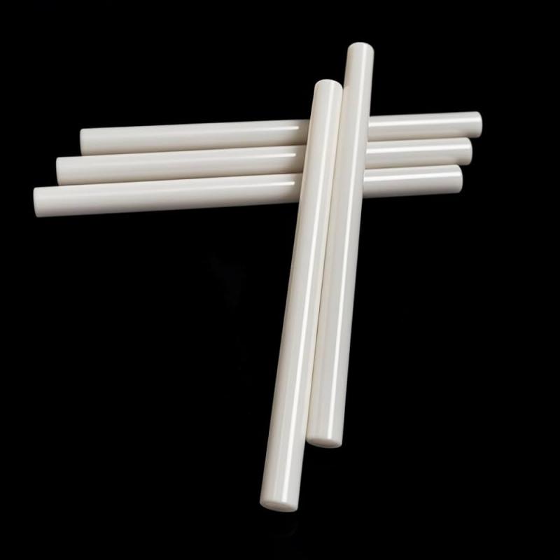
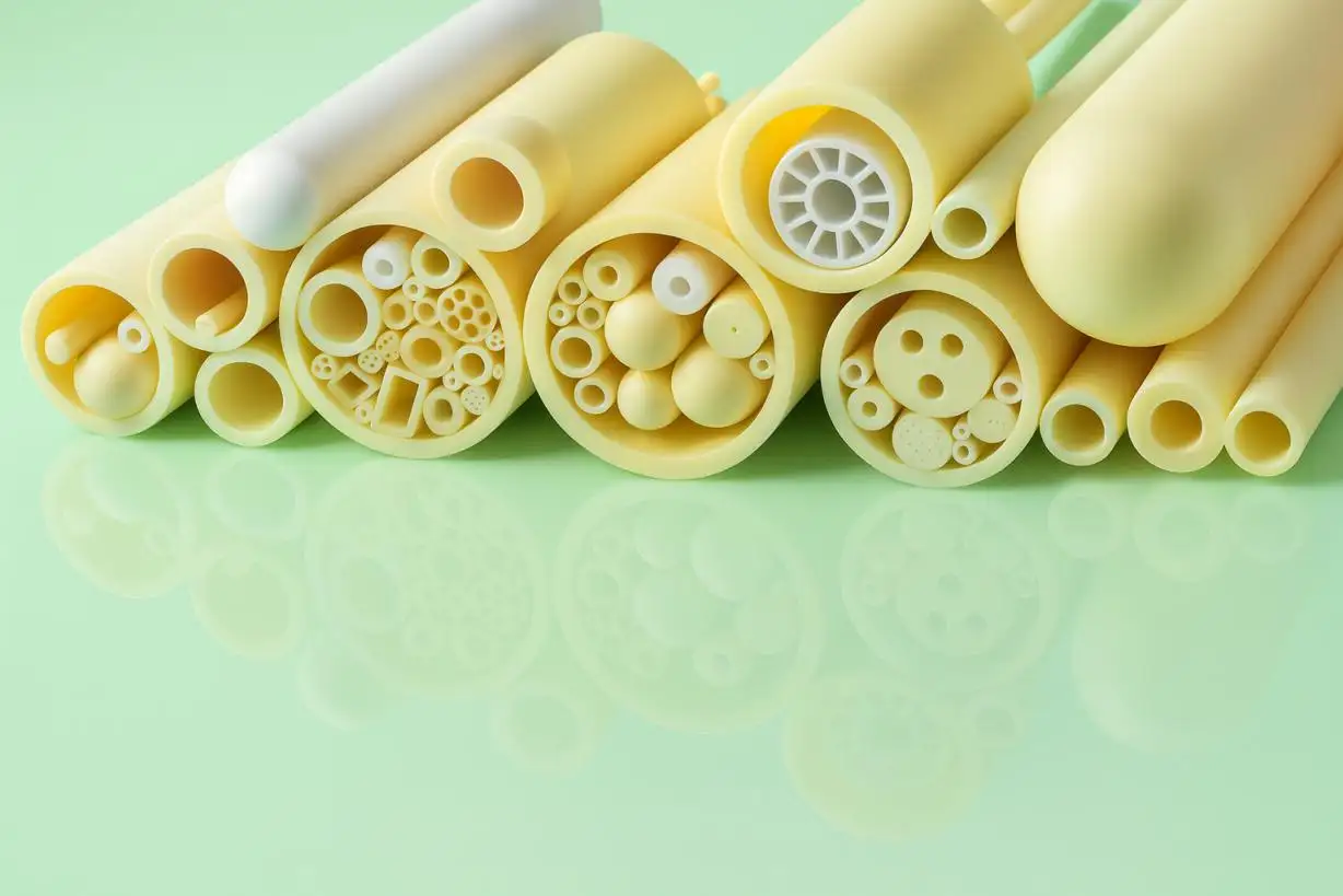
Where traditional metal shafts have issues with corrosion, abrasive wear, electrical conductivity, lubrication or dimensional stability, Ceramic Shafts are used. They can be used to increase the lifespan of equipment, such as pumps, valves, measuring devices, semiconductor equipment and precision mechanisms, due to their hardness and chemical resistance.
But ceramic shafts are no easy drop-in replacement for steel. Their performance relies on the material selection, diameter uniformity, straightness, surface finish, edge state, clearance between shaft and bushing and assembly design. A skilled ceramic shaft producer ought to consider the entire functioning system, instead of simply producing the ceramic shaft itself.
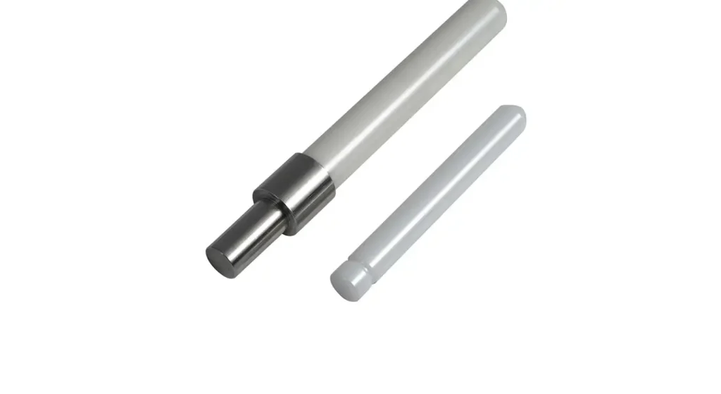
When is a Ceramic Shaft Appropriate?
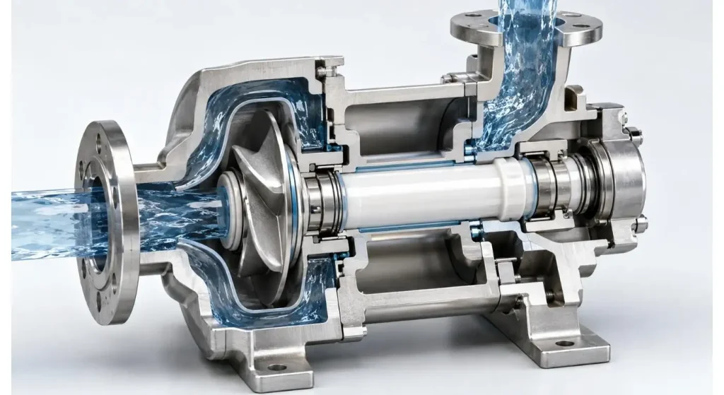
The most beneficial use of ceramic shafts occurs when a metal shaft should prevent some kind of failure repeatedly in the operating environment. They will operate in water, chemicals or other fluids, without the problems of rusting that unprotected steel will experience. Their hard surfaces also provide a smooth surface to prevent abrasive wear against the compatible bearing or bushing.
Common applications include:
- Water and chemical pumps as well as transfer pumps.
- Valves and plungers
- Precision positioning systems
- Measuring probes and inspection instruments are used to measure and inspect.
- Equipment for medical and laboratory purposes
- Semiconductor handling mechanisms
- Fabric and automation equipment.
UPCERA manufactures custom ceramic rods for use in stepped, application-specific, solid and hollow forms, which can be assessed for shaft, guide, plunger and positioning applications.
Select the Shaft Material around the Failure Mode
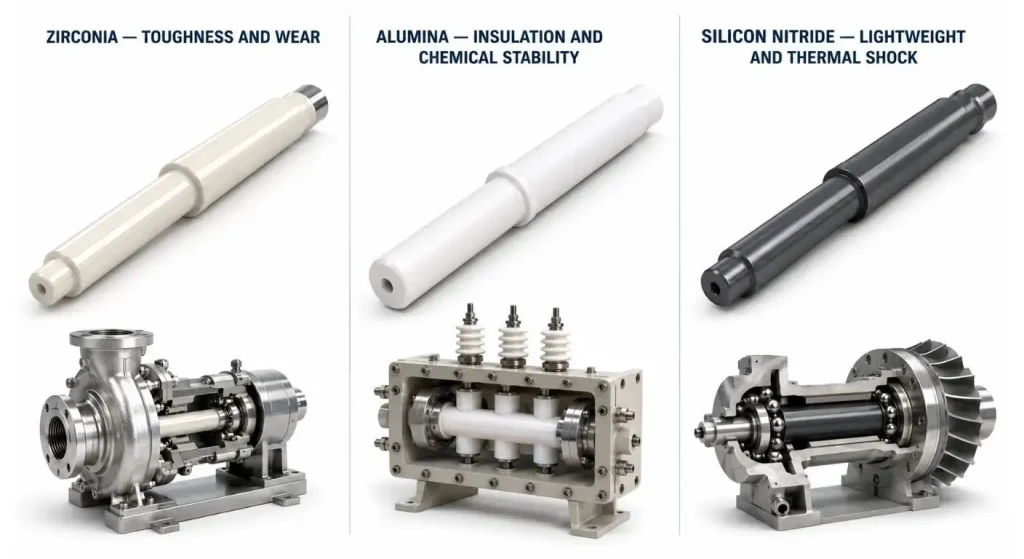
The ceramic-shaft materials commonly used are zirconia and alumina which address different engineering problems.
Zirconia offers a high fracture toughness, wear resistance and a smooth finish. It’s frequently recommended for use on a compact pump shaft, plungers and parts that are subject to mechanical contact or intermittent shock.
Alumina is hard, has a good electrical insulation, is chemically stable and resistant to high temperatures. It can be an economical option for insulating shafts, guides and wear resistant components where there is not likely to be severe impact. When designing for thermal and electrical characteristics, engineers can take advantage of the material characteristics of alumina provided by UPCERA.
For demanding rotating applications requiring low density, strength and thermal-shock resistance, silicon nitride is a material that can be considered. Hardness alone should not be used for final selection as other factors such as load direction, speed, temperature, fluid chemistry and accidental impact should be taken into account.
Consider the Shaft and Bushing to be one system.
Even if a ceramic shaft passes all drawing dimensions, it could fail because of an inappropriate bushing, bearing or housing. It is therefore advisable to design and test the shaft and mating component as a set.
| Observed Problem | Possible System Cause | Item to Review |
| Shaft breaks during assembly | Excessive press fit or edge impact | Clearance, chamfer and installation method |
| Uneven wear track | Shaft or housing misalignment | Runout, concentricity and bearing position |
| Rotation becomes unstable | Excessive operating clearance | Shaft and bushing diameter |
| Localized chipping | Edge loading or hard particles | End design, filtration and contact area |
| Rapid bushing wear | Unsuitable material pairing | Surface finish and mating material |
| Leakage near the shaft | Seal surface or runout problem | Roughness, roundness and alignment |
| Failure after thermal cycling | Expansion mismatch | Housing material and mounting design |
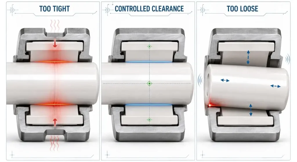
If clearance is too small, it might cause binding during changes in temperature and when particles enter the clearance. Too much clearance can result in vibration, unstable rotation, edge loading and increased wear. The designer must consider such factors as operating temperature, fluid-film characteristics, contamination and thermal expansion of both materials.
A matched ceramic shaft and bushing assembly can minimize the compatibility issues by considering the material combination, working clearance and contact surfaces as a functional pair.
Specify the Dimensions That Control Rotation
The diameter of the ceramic shaft is not the only factor that decides whether or not the ceramic shaft can rotate smoothly. Straightness, roundness, cylindricity, concentricity and runout may also be of paramount importance.
With a stepped shaft, the diameters could each be correct with the sections slightly off axis. This can result in vibration, seal wear or uneven bushing contact. Drawings should clearly define a datum and specify which surfaces are to be concentric.
Some of the critical specifications can be:
- The diameter and fit of the working part.
- Straightness over the supported portion.
- Roundness of bearing surfaces:
- Concentricity between stepped diameters
- Total indicated runout
- Shoulder perpendicularity
- Surface roughness of sliding areas
Tolerances should take into account the true equipment requirement. The request for micron level control on non-functional sections will increase the grinding & inspection cost, but will not give any benefit on performance.
Control Surface Integrity Without Weakening the Shaft
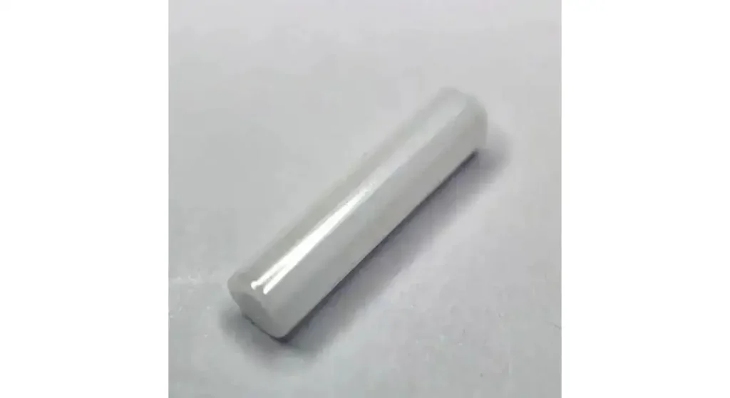
The end dimensions of a sintered ceramic shaft are determined by diamond grinding. Depending on friction, sealing and cleanliness requirements, a lapping or polishing can then be carried out to improve the surface of contact.
Surface smoothness can minimize bushing wear; however, surface smoothness should not be looked at as a stand-alone criteria. During operation, fracture origins may be present in the form of grinding damage, scratches and edge chips and subsurface microcracks.
The ends of the shaft should also be attended to. Chamfers or small radii prevent chipping with insertion and handling. UPCERA’s state-of-the-art Ceramic Machining Guide discusses the importance of controlled grinding, coolant delivery and stable fixturing to safeguard ceramic surface integrity.
Design an Assembly to protect a Brittle Material
Never hammer, bend into alignment or clamp unevenly ceramic shafts. When using press fits and/or too aggressive presses, metal housings can focus stress on a limited ceramic surface.
Depending on the application, assemblies can be designed with controlled clearance or compliant sleeves, adhesives or engineered interference. The loads should be evenly distributed and it is also advisable to avoid sudden changes of sections near high stress locations.
Packaging also matters. Long thin shafts need to be spaced out and braced such that they will not hit each other while being moved.
Validate Performance Before Volume Production
Dimensional inspection verifies that the shaft is in accordance with the drawing, functional testing verifies that the system functions. Prototype testing needs to simulate the expected speed, load, temperature, fluid, contamination and start/stop cycle.
For evaluations: Check for vibration, noise, torque, leaks, wear pattern and temperature. After performing the test inspect both the shaft and bushing. Edge loading or possible misalignment might be seen with an uneven polished track that did not show up during dimensional inspection.
Once validated, the manufacturer should establish stable batches of material, the grinding parameters, inspection frequency and packaging requirements for production.
What to Send a Ceramic Shaft Manufacturer?
A good RFQ will contain a 2D drawing, 3D model (if available), material preference, application conditions, and mating-part information and quantity. Determine all of the critical dimensions and inspection needs.
If the project is for a failed metal or ceramic shaft, include the old part and explain how the part failed. Customers may send their drawings and operating requirements for a manufacturability review and quotation by contacting UPCERA.
Conclusion
Material, geometry, surface integrity, mating clearance and assembly method are all critical for a precision ceramic shaft to be successful. When you select a manufacturer who has experience in ceramic machining and inspection, you are less likely to encounter issues such as vibration, premature wear and brittle failure.
The engineers should design a dimensionally correct shaft-and-bushing system that is tested and proven to be stable under actual operating conditions, rather than only a dimensionally correct shaft.
FAQ
Q1. Which ceramic material is suitable for a pump shaft?
The hardness and chemical stability/cost efficiency of alumina and the toughness and wear resistance of zirconia are often considered. The final choice depends on the fluid chemistry, load, speed and impact risk.
Q2. Is it possible to design ceramic shafts with steps or holes in them?
Yes. The stepped diameters, center holes, slots and end features can be checked from a size, tolerance and machining access point of view.
Q3. Are ceramic shafts lubricated?
There are certain ceramic systems which allow water or process fluid to be used as the lubricant. This varies with the shaft, bushing material, speed and load and fluid condition.
Q4. Is it possible to directly replace a steel shaft with a ceramic shaft?
Not always. Different clearances, edge designs or mounting methods may be necessary due to the higher hardness and lower toughness of ceramics as compared to steel.
Q5. What should be drawn for a custom ceramic shaft?
Include dimensions, datums, tolerances, surface finish, and geometric tolerances and mating part information. The application temperature, speed, load, fluid and amount should also be added.


In This Article
- 1 When is a Ceramic Shaft Appropriate?
- 2 Select the Shaft Material around the Failure Mode
- 3 Consider the Shaft and Bushing to be one system.
- 4 Specify the Dimensions That Control Rotation
- 5 Control Surface Integrity Without Weakening the Shaft
- 6 Design an Assembly to protect a Brittle Material
- 7 Validate Performance Before Volume Production
- 8 What to Send a Ceramic Shaft Manufacturer?
- 9 Conclusion
