 English
 中文
中文







Ceramic-to-Metal Joining for High-Performance Ceramic Components

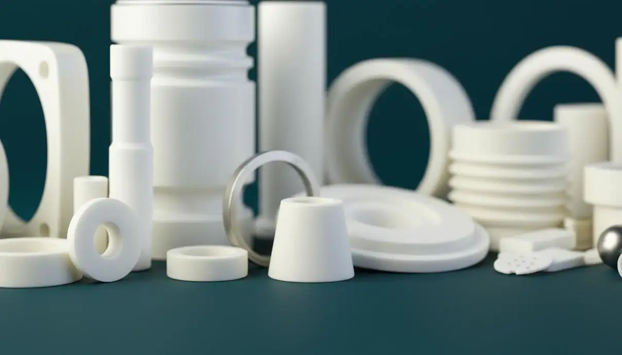
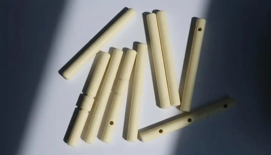
High-performance Ceramic Components are commonly joined to metal when an assembly must combine electrical insulation, wear resistance, corrosion resistance, or thermal stability with the strength, conductivity, machinability, and assembly flexibility of metal.
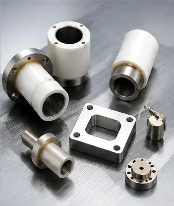
The qualities of ceramics include hardness, insulation, chemical stability, and excellent high-temperature performance. Metals are easily welded, fastened, and are good conductors of electricity. The integration of these materials into larger mechanical systems is straightforward. Engineers make assemblies with fewer parts and multifunctional designs through the combination of both materials.
The joined area of ceramic and metal interfaces is also the most critical. Reliable joining is greatly dependent on controlling the thermal expansion, residual stress, surface finish, joining materials, geometry, and tolerance.
What Is Ceramic-to-Metal Joining?
Ceramic-to-metal joining is the process of integrating Ceramic Components with stainless steel, copper, Kovar, nickel alloys, titanium, or other metals.
Depending on the application, the joint may provide:
•Mechanical load transfer
•Vacuum or hermetic sealing
•Electrical insulation
•Thermal conduction
•Fluid isolation
•Corrosion protection
Joining quality should not be evaluated only by initial bond strength. Temperature cycling, thermal shock resistance, vibration, leakage, chemical compatibility, and long-term fatigue must also be considered.
Why Are Ceramic Components Difficult to Join to Metal?
Difference in Thermal Expansion
Coefficient of thermal expansion values for metals and ceramics are generally not the same. As a result of this, metals will undergo larger expansions and contractions during thermal processes as compared to ceramics.
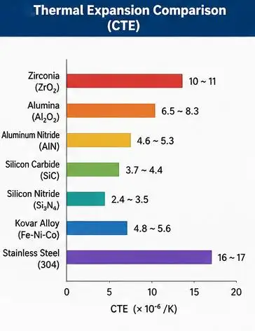
Because Ceramic Components tolerate compression better than localized tensile stress, excessive thermal mismatch may cause cracking, interface separation, or seal failure.
Poor Wettability
Conventional brazing alloys may not wet alumina, zirconia, silicon nitride, or other ceramic surfaces directly. Joining may therefore require:
•Ceramic metallization
•Active metal brazing alloys
•Surface cleaning and activation
•Controlled furnace atmosphere
•Precise joining temperature
Brittle Material Behavior
Unlike metals, ceramics have limited plastic deformation. Sharp corners, thin walls, rigid metal sleeves, and uneven joint loading can create local stress concentrations.
Precision Requirements
Flatness, parallelism, surface roughness, hole size, concentricity, and assembly clearance directly affect filler-metal flow and final alignment.
Common Ceramic-to-Metal Joining Methods
| Method | Principle | Advantages | Limitations |
| Metallization and Brazing | A functional metal layer is applied before brazing | Stable joint and possible hermetic sealing | Requires controlled metallization quality |
| Active Metal Brazing | Active elements such as titanium react with the ceramic surface | May eliminate a separate metallization step | Sensitive to temperature, atmosphere, and filler thickness |
| Adhesive Bonding | Epoxy or high-temperature adhesive joins the parts | Low processing temperature and simple assembly | Limited temperature and chemical resistance |
| Mechanical Joining | Press fits, threads, clamps, or retaining rings are used | Removable and does not require furnace processing | May create stress concentration |
| Diffusion Bonding | Heat and pressure promote interfacial diffusion | Thin interface and good high-temperature stability | Requires specialized equipment |
How Metallized Ceramic Components Are Produced
Metallized Ceramic Components serve a purpose beyond aesthetics. The metallization process results in a surface that enhances wettability for brazing.
The process typically involves:
- Ceramic forming and sintering
- Precision grinding of the joining surface
- Surface cleaning and activation
- Preparation of the metallization layer
- Nickel plating or a different interfacial layer
- Placement of ceramics and metals
- Brazing in a vacuum or inert gas atmosphere
- Inspection for compliance in dimensions and strength and for leakage
The metallized layer serves to control the interfacial reaction and provides a more uniform distribution of filler along the interfacial region as well as a more uniform and gradual transition from ceramic to metal.
Key Considerations for the Design of Ceramic-to-Metal Assemblies
Selection of Materials for Joining Ceramics to Metals
Materials should be selected based on specific data for the constituent materials as opposed to broad, qualitative descriptions. For ceramic-to-metal assemblies, the coefficients of thermal expansion, fracture toughness, flexural strength, and thermal conductivity define the residual stresses, joining temperature, interface design, and the reliability of the assembly in service.
| Ceramic Material | Key Properties | Joining Considerations and Applications |
| Alumina, 96–99.5% Al₂O₃ | Flexural strength: 296–310 MPa; toughness: 3–4 MPa·√m; conductivity: 24–30 W/m·K; CTE: 6.5–8.3 × 10⁻⁶/K; resistivity: >10¹⁴ Ω·cm | Good insulation, wear resistance, and metallization compatibility. Used for insulators, vacuum feedthroughs, sensors, and metallized Ceramic Components. |
| Zirconia, ZrO₂ | 750–1,470 MPa; 4–10 MPa·√m; 2.7–3 W/m·K; CTE: 10–11 × 10⁻⁶/K | High strength and toughness. Suitable for sleeves, inserts, pumps, and impact-resistant bonded parts. |
| Aluminum Nitride, AlN | 220–450 MPa; about 3 MPa·√m; 67–170 W/m·K; CTE: 4.6–5.3 × 10⁻⁶/K | Combines heat transfer with insulation. Used in power electronics, semiconductor parts, and heat spreaders. |
| Silicon Nitride, Si₃N₄ | 580–1,020 MPa; 4–7 MPa·√m; 25–90 W/m·K; CTE: 2.4–3.5 × 10⁻⁶/K | High strength and thermal-shock resistance. Often requires compliant interlayers during brazing. |
| Silicon Carbide, SiC | 450–540 MPa; 2–5 MPa·√m; about 200 W/m·K; CTE: 3.7–4.4 × 10⁻⁶/K | Excellent heat, wear, and corrosion resistance. Common in semiconductor equipment, seals, pumps, and thermal structures. |
Impacts of Different Factors on Joint Design
All aspects of joining must be considered when bonding ceramics to metals.
•CTE Mismatch: When ceramic and metal materials have significantly different coefficients of thermal expansion, suitable metal selection and compliant interlayers may be required to reduce residual stress.
•Fracture Toughness: During the bonding process, the presence of sharp edges will be tolerated with greater stress by ZrO2 and Si3N4.
•Thermal Conductivity: For the case of the dissipation of heat, AlN and SiC are the ceramics of choice.
•Electrical Behavior: Al2O3, AlN, and Si3N4 are insulating ceramics, whereas SiC is insulating in some grades but not in others.
•Strength after joining: Final strength depends on metallization, brazing alloy, clearance, residual stress, and thermal cycling.
These values are references; final Ceramic Components require application-specific evaluation.
Joint Geometry and Clearance
Good ceramic-to-metal designs generally:
•Avoid sharp corners in the ceramic joining area
•Use radii and gradual transitions
•Keep the assembly as symmetrical as possible
•Prevent rigid metal structures from over-constraining the ceramic
•Position joints away from high tensile loads
•Provide space for brazing-alloy flow
Joint clearance affects capillary action, filler distribution, interface thickness, alignment, and residual stress. Excessively small gaps may prevent complete filling, while oversized gaps may produce a thick and unstable joint layer.
Surface Finish and Flatness
Controlled surfaces improve metallization uniformity, assembly contact, filler thickness, and dimensional consistency. They also lessen local discontinuities that may cause stress concentration.
The Impact of Precision Machining on Joining Quality
Because of its ability to adjust joint clearances and surface contact as well as to properly align the surfaces and control the distribution of stress prior to the brazing or bonding process, precision machining optimizes the ceramic-to-metal joining process.
Poorly machined Ceramic Components may cause:
• Ceramic and metal misalignment
• Uneven braze thickness
• Local filler-metal voids
• Tilted assemblies
• Sealing-surface failure
• Final dimensions outside tolerance
Important features include inner and outer diameters, stepped-hole position, concentricity, flatness, perpendicularity, parallelism, and joining-surface roughness.
Common Joining Failures
| Failure | Possible Cause | Improvement |
| Ceramic cracking | Thermal mismatch, sharp corners, rapid cooling | Improve material matching and thermal cycles |
| Interface delamination | Contamination, poor wetting, discontinuous metallization | Improve cleaning and process control |
| Braze voids | Uneven clearance or insufficient filler | Optimize joint geometry and furnace conditions |
| Leakage | Cracks, pores, or incomplete interfaces | Add hermetic and interface inspection |
| Distortion | Asymmetric design or fixture restriction | Improve fixture and heating design |
| Joint corrosion | Incompatible alloy or metal | Select materials based on the operating medium |
Applications of Ceramic-to-Metal Components
Ceramic metal bonding parts are used in:
• Wear-resistant bushings, nozzles, valves, and guides
• Metallized electrical insulators and high-voltage assemblies
• Semiconductor vacuum and wafer-handling equipment
• Medical fluid-control and instrument components
• Corrosion-resistant chemical-processing systems
UPCERA Support for Custom Ceramic Components
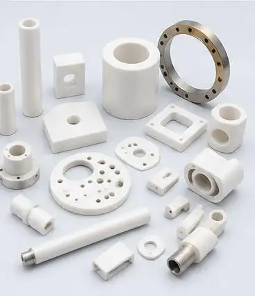
Reliable joining begins with a dimensionally stable ceramic substrate. UPCERA specializes in high-precision custom Ceramic Components, including bushings, nozzles, square-hole parts, metallized parts, engraved components, ceramic-to-metal bonded parts, and complex non-standard structures.
Available manufacturing capabilities include:
| Capability | Typical Range |
| Tube and Rod Length | Up to 1,000 mm |
| Plate Size | Up to 400 × 400 mm |
| Custom Shape Size | Up to 300 mm |
| Minimum Wall Thickness | 0.1–0.2 mm |
| Minimum Drilled Hole | φ0.4 mm |
| Minimum Thread | M2 |
| Surface Roughness | Ra 0.02–Ra 0.2 |
| Small OD Accuracy | Up to ±0.002 mm |
| Small ID Accuracy | Up to ±0.001 mm |
| Concentricity | 0.002 mm |
| Flatness | 0.003 mm |
Actual tolerances depend on material, geometry, wall thickness, hole depth, and component size. Thin-wall, long, deep-hole, and large-format parts should be evaluated individually.
UPCERA combines forming, controlled sintering, precision grinding, drilling, threading, metallization, engraving, printing, dimensional inspection, and ceramic-to-metal assembly support.
Concluding Remarks
Due to factors such as types of loading, geometry, and temperature, sealing and many others, there are numerous methods of joining materials. Reliable Ceramic Components require specific machining and preparation of surfaces and parameters that are tightly controlled.
Kindly provide indications of operating conditions, tolerances, and sketches. Before production, UPCERA will evaluate manufacturability, joint clearance, and stress specifications.
FAQs
Q1. Can UPCERA make thin wall ceramic components?
Yes, UPCERA can make parts with thin wall thickness in the range of 0.1 to 0.2 mm. The exact thickness depends on the material, size, geometry, and the requirements of the specific application.
Q2. Can UPCERA make ceramic-to-metal bonded parts?
Yes, UPCERA can make parts with ceramic-to-metal bonding where the ceramic part must provide electrical insulation and needs to have wear resistance, corrosion resistance, and/or provide structural strength and/or be integrated with metal parts.
Q3. Can UPCERA make metallized ceramic components?
Yes, UPCERA makes metallized ceramic components to provide electrical insulation and bonding for brazing, assemblies, and the joining of components in vacuum and other sealing systems.
Q4. What are the available ceramic materials?
The selection of materials is application dependent. Commonly, UPCERA uses alumina, zirconia, aluminum nitride, silicon nitride, and silicon carbide.
Q5. What is UPCERA’S minimum drilled hole size?
Minimum drilled hole size is approximately φ0.4 mm for UPCERA, depending on the ceramic material, hole depth, wall thickness, and the required tolerance.


In This Article
- 1 What Is Ceramic-to-Metal Joining?
- 2 Why Are Ceramic Components Difficult to Join to Metal?
- 3 Common Ceramic-to-Metal Joining Methods
- 4 How Metallized Ceramic Components Are Produced
- 5 Key Considerations for the Design of Ceramic-to-Metal Assemblies
- 6 The Impact of Precision Machining on Joining Quality
- 7 UPCERA Support for Custom Ceramic Components
